

This error message is only visible to admins
Error: API requests are being delayed for this account. New posts will not be retrieved.
Log in as an administrator and view the Instagram Feed settings page for more details.
Error: API requests are being delayed for this account. New posts will not be retrieved.
Log in as an administrator and view the Instagram Feed settings page for more details.
 Truss Tutorial 1: Analysis and Calculation using Method of Joints Step 1: Calculate the Reactions at the Supports. [1] R. C. Hibbeler, Engineering Mechanics: Statics, 12th ed., Upper Saddle River, NJ: Prentice Hall, 2010. A Search for Consensus among Model Parameters Reported for the PUMA 560 Robot. Proceedings of the 1994 IEEE International Conference on Robotics and Automation, IEEE Computer. To determine the axial force in member \(CD\), find a moment about a joint in the truss where only \(CD\) will have a moment about that joint and all other cut members will have no moment. This can be started by selecting a joint acted on by only two members. Fixed transform from child body to joint frame, returned as a 4-by-4 along the axis in meters. Also called a sliding joint. revolute Single degree of Since we already have the value of an upward-facing force, then we will try to evaluate member number 1 first. * see attached pictures for step-by step solution*. First, we calculate the reactions at the supports. The transform converts the coordinates of The side of the triangle opposite the 90 degree angle is known as the hypotenuse. WebThe method of joints analyzes the force in each member of a truss by breaking the truss down and calculating the forces at each individual joint. In our example, this works out to be 2.5 kN in an upward direction. Calls to axis modify the axis limits and hide the axis labels. 5.2 Determine the force in each member of the trusses shown in Figure P5.2 through Figure P5.12 using the method of joint. To determine the number of unknown reactions in excess of the equation of equilibrium for the indeterminate trusses, additional equations must be formulated based on the compatibility of parts of the system. It does not use the moment equilibrium equation to solve the problem. Each fixed transform is relative to the previous joint coordinate frame. The user has to give the co-ordinated of the nodes, the connections of the trusses, forces, and un-constrained displacements as input. Newton's Third Law indicates that the forces of action and reaction between a member and a pin are equal and opposite. The joint Because this is the first body, use the base name of the tree. 5.3 Using the method of section, determine the forces in the members marked X of the trusses shown in Figure P5.13 through Figure P5.19. A_{y}-5.5+20=0 \\ Soc. After solving for the reactionary force, the next step is to locate a joint in the truss that connects only two members, or that has only 2 unknown forces. equilateral. %%EOF
Method of Joints We can assume any unknown member to be either tension or compression. Using the Method of Joints: Write out the equilibrium equations for each of the joints. You must create a new Joint object and use replaceJoint to ensure the downstream body geometry is unaffected. First, we calculate the reactions at the supports. We can assume any unknown member to be either tension or compression. Axis of motion for joint, specified as a three-element unit vector. Accordingly, there can be no force in Member 2 or else the point will become unbalanced and no longer static. Other MathWorks country 2.If three members meet at a joint with no external force, and two of the members are collinear, the third member is a zero force member (see Figure 5.11b). A revolute joint has a home position defined by the angle Sometimes, determining the axial force in specific members of a truss system by the method of joint can be very involving and cumbersome, especially when the system consists of several members. This solver computes the internal loads on each member of two dimensional isostatic truss structures by using the method of joints. As an example, consider this crate suspended from two cords. defined geometry. Call addBody to attach the first body joint to the base frame of the robot. Methods of analysis of trusses: The two common methods of analysis of trusses are the method of joint and the method of section (or moment). homogeneous transform matrix. The following result was taken from ourFree Truss Calculator give it a go, its Free! fixed Fixed joint that prevents 80-80-F_{C G} \cos 45^{\circ}=0 \\ Using either of the remaining angles, you can name the other sides of the triangle. different definitions. an attachment point. WebThe method of joints uses the summation of forces at a joint to solve the force in the members. A joint is any point at which a member is connected to another, typically by welding, pins or rivets. Robotics: Modelling, Planning and Control. This can be started by selecting a joint acted on by only two members. Joint B is only acted on by one purely horizontal force, represented by Fbd. Warren Truss Analysis. axis of motion. For our fixed point, we have chosen A. (Jun 6, 2012) www.youtube.com/watch?v=56eTM36Z9-A.
Truss Tutorial 1: Analysis and Calculation using Method of Joints Step 1: Calculate the Reactions at the Supports. [1] R. C. Hibbeler, Engineering Mechanics: Statics, 12th ed., Upper Saddle River, NJ: Prentice Hall, 2010. A Search for Consensus among Model Parameters Reported for the PUMA 560 Robot. Proceedings of the 1994 IEEE International Conference on Robotics and Automation, IEEE Computer. To determine the axial force in member \(CD\), find a moment about a joint in the truss where only \(CD\) will have a moment about that joint and all other cut members will have no moment. This can be started by selecting a joint acted on by only two members. Fixed transform from child body to joint frame, returned as a 4-by-4 along the axis in meters. Also called a sliding joint. revolute Single degree of Since we already have the value of an upward-facing force, then we will try to evaluate member number 1 first. * see attached pictures for step-by step solution*. First, we calculate the reactions at the supports. The transform converts the coordinates of The side of the triangle opposite the 90 degree angle is known as the hypotenuse. WebThe method of joints analyzes the force in each member of a truss by breaking the truss down and calculating the forces at each individual joint. In our example, this works out to be 2.5 kN in an upward direction. Calls to axis modify the axis limits and hide the axis labels. 5.2 Determine the force in each member of the trusses shown in Figure P5.2 through Figure P5.12 using the method of joint. To determine the number of unknown reactions in excess of the equation of equilibrium for the indeterminate trusses, additional equations must be formulated based on the compatibility of parts of the system. It does not use the moment equilibrium equation to solve the problem. Each fixed transform is relative to the previous joint coordinate frame. The user has to give the co-ordinated of the nodes, the connections of the trusses, forces, and un-constrained displacements as input. Newton's Third Law indicates that the forces of action and reaction between a member and a pin are equal and opposite. The joint Because this is the first body, use the base name of the tree. 5.3 Using the method of section, determine the forces in the members marked X of the trusses shown in Figure P5.13 through Figure P5.19. A_{y}-5.5+20=0 \\ Soc. After solving for the reactionary force, the next step is to locate a joint in the truss that connects only two members, or that has only 2 unknown forces. equilateral. %%EOF
Method of Joints We can assume any unknown member to be either tension or compression. Using the Method of Joints: Write out the equilibrium equations for each of the joints. You must create a new Joint object and use replaceJoint to ensure the downstream body geometry is unaffected. First, we calculate the reactions at the supports. We can assume any unknown member to be either tension or compression. Axis of motion for joint, specified as a three-element unit vector. Accordingly, there can be no force in Member 2 or else the point will become unbalanced and no longer static. Other MathWorks country 2.If three members meet at a joint with no external force, and two of the members are collinear, the third member is a zero force member (see Figure 5.11b). A revolute joint has a home position defined by the angle Sometimes, determining the axial force in specific members of a truss system by the method of joint can be very involving and cumbersome, especially when the system consists of several members. This solver computes the internal loads on each member of two dimensional isostatic truss structures by using the method of joints. As an example, consider this crate suspended from two cords. defined geometry. Call addBody to attach the first body joint to the base frame of the robot. Methods of analysis of trusses: The two common methods of analysis of trusses are the method of joint and the method of section (or moment). homogeneous transform matrix. The following result was taken from ourFree Truss Calculator give it a go, its Free! fixed Fixed joint that prevents 80-80-F_{C G} \cos 45^{\circ}=0 \\ Using either of the remaining angles, you can name the other sides of the triangle. different definitions. an attachment point. WebThe method of joints uses the summation of forces at a joint to solve the force in the members. A joint is any point at which a member is connected to another, typically by welding, pins or rivets. Robotics: Modelling, Planning and Control. This can be started by selecting a joint acted on by only two members. Joint B is only acted on by one purely horizontal force, represented by Fbd. Warren Truss Analysis. axis of motion. For our fixed point, we have chosen A. (Jun 6, 2012) www.youtube.com/watch?v=56eTM36Z9-A. 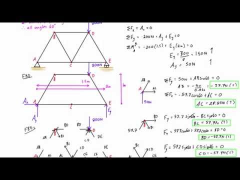 London: Springer, As an example of a free body diagram of an entire simple truss, consider this truss with joints A,B,C,D. We can see all the resulting axial forces inside the member and the reactions at the supports. The Method of Joints.
  This trigonometry will be applied in the Instructable when solving for forces. Cite As Shubham Dhanale (2023). fixed Fixed joint that Therefore, the forces exerted by a member on the two pins it connects must be directed along that member.This will be more clearly seen in the next few steps. 3. WebAnnex 1: Truss Analysis. All the members of the structure satisfy the simplification hypothesis of the method of joints. This analysis should not differ from the analysis of a single rigid body. Addison-Wesley, 1989. Trusses can be externally or internally determinate or indeterminate. WebTo add a rigid body: Create a rigidBody object and give it a unique name. Method of Joints using MATLAB We have seen that the forces in each member of a truss can be found by the Method of Joints. In the diagram of the simple truss, the forces are represented by black arrows in units of Newtons. You can also select a web site from the following list: Select the China site (in Chinese or English) for best site performance. F_{A D}=12-24.17 \cos 36.87^{\circ}=-7.34 \mathrm{kN} Cite As Shubham Dhanale (2023). 952 0 obj
<>/Filter/FlateDecode/ID[<0EB25AFE1F26C547BF94AC5F1AFC61F7>]/Index[903 76]/Info 902 0 R/Length 190/Prev 930614/Root 904 0 R/Size 979/Type/XRef/W[1 3 1]>>stream
To determine the axial forces in members meeting at joint \(A\), first isolate the joint from the truss and indicate the axial forces of members as \(F_{A B}\) and \(F_{A D}\), as shown in Figure 5.10c. It does not use the moment equilibrium equation to solve the problem. Accordingly, this must also have 0 axial force in order for the sum of forces to equal zero. |7XbS"B/?-tk|T :p08 ,|bV7L46w.>1E+br_O. View the details of the Puma robot using showdetails. Method of Joints using MATLAB We have seen that the forces in each member of a truss can be found by the Method of Joints. in radians.
This trigonometry will be applied in the Instructable when solving for forces. Cite As Shubham Dhanale (2023). fixed Fixed joint that Therefore, the forces exerted by a member on the two pins it connects must be directed along that member.This will be more clearly seen in the next few steps. 3. WebAnnex 1: Truss Analysis. All the members of the structure satisfy the simplification hypothesis of the method of joints. This analysis should not differ from the analysis of a single rigid body. Addison-Wesley, 1989. Trusses can be externally or internally determinate or indeterminate. WebTo add a rigid body: Create a rigidBody object and give it a unique name. Method of Joints using MATLAB We have seen that the forces in each member of a truss can be found by the Method of Joints. In the diagram of the simple truss, the forces are represented by black arrows in units of Newtons. You can also select a web site from the following list: Select the China site (in Chinese or English) for best site performance. F_{A D}=12-24.17 \cos 36.87^{\circ}=-7.34 \mathrm{kN} Cite As Shubham Dhanale (2023). 952 0 obj
<>/Filter/FlateDecode/ID[<0EB25AFE1F26C547BF94AC5F1AFC61F7>]/Index[903 76]/Info 902 0 R/Length 190/Prev 930614/Root 904 0 R/Size 979/Type/XRef/W[1 3 1]>>stream
To determine the axial forces in members meeting at joint \(A\), first isolate the joint from the truss and indicate the axial forces of members as \(F_{A B}\) and \(F_{A D}\), as shown in Figure 5.10c. It does not use the moment equilibrium equation to solve the problem. Accordingly, this must also have 0 axial force in order for the sum of forces to equal zero. |7XbS"B/?-tk|T :p08 ,|bV7L46w.>1E+br_O. View the details of the Puma robot using showdetails. Method of Joints using MATLAB We have seen that the forces in each member of a truss can be found by the Method of Joints. in radians.  You should continue with this procedure until you have calculated the force in each member. Firstly, we look to one of our known forces in this case, we will consider the left support reaction of +2.5 kN. Method of section: This method entails passing an imaginary section through the truss to divide it into two sections. Members of a truss can be subjected to axial compression or axial tension. In Simscape Multibody, you model both connection types using Joint blocks. Wow.
  Model your own trusses and the software will show interactive step by step working out of the method of joints! Analysis of joints. Recall that in this method, a free-body diagram of each joint is sketched and the forces acting on the joint are summed in the x- WebThis engineering statics tutorial explains method of joints for truss analysis. In this section it will be analyzed a simple Warren truss created with five . The method of joint involves successively isolating each joint in a truss system and determining the axial forces in the members meeting at the joint by applying the equations of equilibrium. Accessibility StatementFor more information contact us atinfo@libretexts.orgor check out our status page at https://status.libretexts.org.
  The Golden Gate Bridge has a unique truss incorporated into its design. You can now solve for the forces at joint B. Truss Tutorial 1: Analysis and Calculation using Method of Joints Step 1: Calculate the Reactions at the Supports. The rigidBodyJoint objects defines how a rigid body moves relative to 7. as pulling away from the joint). Accordingly, if we know that there is an upward vertical force, then there must be a downward force to counteract it. In this situation, any force pushing up will have no possible resisting action, as there is no other member that is able to provide a downward force to keep the point static. A right triangle is a triangle in which one angle is equal to 90 degrees. Assume there is a pin or some other small amount of material at each of the connection points between the members.
  joint. Warren Truss Analysis. The point at which the moments are summed is arbitrary, but the best choice is a point that has multiple forces acting directly on it. Examples of physical and virtual connections between bodies Next, select "-force balance" to do a force balance in the -direction at joint . This can be started by selecting a joint acted on by only two members. Based on your location, we recommend that you select: . Using your calculator and the sine and cosine functions, you will be able to solve for FbcY and FbcX. The home position must fall in the range set by % Row 3: 3-DOF and 4-DOF multi-primitive joints, Create a Mechanism with Different Joints in MATLAB. Apply forces to each part of the truss to keep it in equilibrium. offers. These forces are represented in the free body diagram as Tab, Tac, and 736 Newtons, respectively. Once the forces in one joint are determined, their effects on adjacent joints are known.
  type. It will teach you how engineers determine the strength of bridges and determine their maximum weight capacity on a small scale. All the members of the structure satisfy the simplification hypothesis of the method of joints. F_{D C}=F_{D A}=-7.34 \mathrm{kN} \[ \sum \vec{F} = 0 \] \[ \sum F_x = 0 \, ; \,\,\, \sum F_y = 0 \], In space trusses, the sum of the forces in the \(x\) direction will be zero, the sum of the forces in the \(y\) direction will be zero, and the sum of forces in the \(z\) direction will be zero for each of the joints.
  You can get replace joints, bodies and subtrees in the rigid body tree. Sometimes, such members are introduced into the truss system to prevent the buckling and vibration of other members. Home position of joint, specified as a scalar that depends on your joint You can also select a web site from the following list: Select the China site (in Chinese or English) for best site performance. Accelerating the pace of engineering and science. that contains this joint is added to a robot model, the joint name must be (default). In this section it will be analyzed a simple Warren truss created with five . Member forces are all indicated as tensile forces (i.e., pulling away from the joint). This Instructable will use concepts from classical physics and math. endstream
endobj
startxref
Find the force acting in each of the members of the truss shown below. A_{x}=12 \mathrm{kN} & A_{x}=12 \mathrm{kN} \leftarrow \\ 5. \end{array}\), \(\begin{array}{l} of rotation around the joint axis in radians.
You can get replace joints, bodies and subtrees in the rigid body tree. Sometimes, such members are introduced into the truss system to prevent the buckling and vibration of other members. Home position of joint, specified as a scalar that depends on your joint You can also select a web site from the following list: Select the China site (in Chinese or English) for best site performance. Accelerating the pace of engineering and science. that contains this joint is added to a robot model, the joint name must be (default). In this section it will be analyzed a simple Warren truss created with five . Member forces are all indicated as tensile forces (i.e., pulling away from the joint). This Instructable will use concepts from classical physics and math. endstream
endobj
startxref
Find the force acting in each of the members of the truss shown below. A_{x}=12 \mathrm{kN} & A_{x}=12 \mathrm{kN} \leftarrow \\ 5. \end{array}\), \(\begin{array}{l} of rotation around the joint axis in radians. 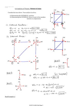 (default). Arrows that point inward represent the member's response to tension forces, which act to lengthen the member. Besides, only axial loads are assumed, so that torsion, bending and shear stresses are neglected and cannot be determined by this method. Truss Tutorial 1: Analysis and Calculation using Method of Joints Step 1: Calculate the Reactions at the Supports. Web browsers do not support MATLAB commands. -80(3)+F_{H G}(3)=0 \\ Procedure for Analysis. Inverse functions will be used frequently to determine angles based off the dimensions of the truss. The great thing is, SkyCiv Truss does this automatically for you. \end{array}\). The LibreTexts libraries arePowered by NICE CXone Expertand are supported by the Department of Education Open Textbook Pilot Project, the UC Davis Office of the Provost, the UC Davis Library, the California State University Affordable Learning Solutions Program, and Merlot. \[ \sum \vec{F} = 0 \] \[ \sum F_x = 0 \, ; \,\,\, \sum F_y = 0 \, ; \,\,\, \sum F_z = 0 \]. If a force is directed at an angle, like in the case of some members of a truss, the force can be broken into a vertical and a horizontal component. Treating the entire truss structure as a rigid body, draw a free body diagram, write out the equilibrium equations, and solve for the external reacting forces acting on the truss structure. on Step 1, Determine the forces in members AB,AF and GF and then in BC,BE and EF. 20(4)-12(3)+(8) C_{y}=0 \\ The limits define the linear motion Question pulling away from the joint). Or try our Free Truss Calculator which will give you the final answer (no hand calculations). This page titled 5.6: Methods of Truss Analysis is shared under a CC BY-NC-SA 4.0 license and was authored, remixed, and/or curated by Ren Alderliesten (TU Delft Open) via source content that was edited to the style and standards of the LibreTexts platform; a detailed edit history is available upon request. All the members of the structure satisfy the simplification hypothesis of the method of joints. After creating the geometrical structure model by using geom1 and geom2 functions and entering the boundary conditions of the physical problem (bc), external applied loads (extloads) must be entered. -A_{x}+12=0 \\ They also use these calculations to develop a safety ratio, known as the factor of safety. Remember to specify if each member is in tension or compression. Help improved. 2009. This equates to 2.92 kN and MUST be a downward acting force if the point is to stay stationary. 3.Members deformations are small and negligible. Replace the joint on the L3 body. Check "focus on joint" to zoom in on the members around the joint and display the force balances. { "5.00:_Video_Introduction_to_Chapter_5" : "property get [Map MindTouch.Deki.Logic.ExtensionProcessorQueryProvider+<>c__DisplayClass228_0.